Electricity powers our modern world, from the lights in our homes to the devices we use every day. But How Does Electricity Travel? Understanding the fundamentals of electrical circuits is key to unraveling this mystery. This guide will break down the essentials of electrical circuits, including the flow of electricity, circuit diagrams, and the differences between series and parallel circuits. Let’s embark on a journey to explore the fascinating world of circuitry.
The Basics of Electrical Flow
To grasp the concept of electrical flow, it’s crucial to start with the basics. Electricity is fundamentally the flow of electric charge, typically the movement of electrons through a conductive material. These electrons migrate from areas with a negative charge concentration towards areas with a positive charge concentration, resulting in an electric current.
The Role of Electrons in Electrical Flow
In conductors, such as metals, some electrons are not tightly bound to individual atoms and are free to move. These “free electrons” can drift between atoms. When a voltage, or potential difference, is applied across a conductor, it generates an electric field. This field exerts a force on the free electrons, propelling them through the conductor. This directed movement of electrons is what we define as electricity.
The Importance of a Complete Circuit
For electrons to flow continuously, they require a complete path, known as a circuit. This circuit must extend from a source of negative charge, through the conductor, and back to the source of positive charge. A simple example is a circuit consisting of a light bulb, a battery, a switch, and connecting wires. Closing the switch completes the circuit, allowing the battery’s negative terminal to repel electrons (due to the repulsion of like charges), sending them through the wire to the bulb. As a result, the bulb illuminates, and the electrons continue their journey back to the positive terminal. Conversely, when the switch is open, the circuit is incomplete, and electricity cannot flow.
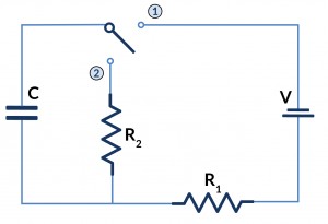 A simple circuit with a battery, switch, and lightbulb illustrating how electricity flows.
Conventional Current vs. Electron Flow
Historically, the direction of electrical current was defined as the flow of positive charge from the positive terminal to the negative terminal. This is known as “conventional current,” and it predates the discovery of electrons. However, “electron flow” recognizes that electrons, which carry a negative charge, actually move from the negative to the positive terminal. Despite this difference, both models are valid and used depending on the context.
Circuit Integrity and its Effect on Flow
The completeness of the electrical path is critical for the flow of electricity. Any break in the circuit, whether intentional (like a switch) or accidental (like a damaged component), will interrupt the flow of electrons and stop the current. The term “circuit” emphasizes the circular nature of the path, highlighting the requirement for a closed loop for continuous electricity flow.
Understanding electron movement within a circuit paves the way for understanding more intricate electrical concepts, such as the behavior of series and parallel circuits. A fundamental principle to remember is that electricity flow is analogous to water flowing downhill, moving from areas of high concentration (negative charge) to areas of low concentration (positive charge).
Visualizing Electrical Flow with Circuit Diagrams
Electrical circuits are the building blocks of modern technology. They are present in a wide range of devices, from smartphones to kitchen appliances. A circuit consists of a path or loop through which electrical current flows. This path can be closed (a complete loop) or open (broken), and it may contain various components such as resistors, transistors, capacitors, and wires.
The Role and Importance of Circuit Diagrams
Circuit diagrams, also called schematic diagrams, are visual representations of electrical circuits. They utilize standardized symbols to depict electrical components and lines to represent the connections between them. These diagrams are essential for designing, constructing, and maintaining electrical and electronic equipment.
Circuit diagrams serve as a universal language, enabling individuals from diverse backgrounds and locations to understand circuit functionality. This standardized communication is vital for sharing designs, troubleshooting circuit issues, and ensuring the safety and correctness of electrical systems.
Reading Circuit Diagrams: A Step-by-Step Guide
To effectively interpret circuit diagrams, familiarity with component symbols is essential. These symbols are interconnected by lines that illustrate the pathways between components, effectively mapping the flow of current within the circuit. The key is to identify the symbols and then trace the lines, which represent the wires connecting the components.
Common Circuit Symbols and Their Meanings
Circuit symbols act as a shorthand, providing a concise way to identify the components within a circuit diagram. Mastering these symbols unlocks a deeper understanding of the circuit’s functionality.
Essential Circuit Symbols:
- Resistor: Represented by a rectangle or a zigzag line, a resistor restricts the flow of electrical current.
- Capacitor: Depicted by two parallel lines with a gap, a capacitor stores electrical energy.
- Voltage Source or Battery: Illustrated by a series of alternating short and long lines, a battery provides the power source for the circuit.
- Light Bulb: Shown as a circle with a cross inside, a light bulb emits light when current passes through it.
Advanced Circuit Symbols:
As circuits become more complex, you will encounter symbols for diodes, transistors, and other components. Each symbol represents specific characteristics of the component it describes.
Learning and Applying Circuit Symbols
Mastering circuit symbols is a fundamental step towards understanding electronics. They form the language of electronics, enabling the creation and interpretation of complex circuit diagrams. Whether designing or analyzing a circuit, the ability to recognize and understand these symbols is paramount.
Electricity Flow in Series and Parallel Circuits
Two primary types of electrical circuits exist: series and parallel circuits. Each type possesses unique characteristics, advantages, and disadvantages.
Series Circuits: A Single Path for Electricity
In a series circuit, components are connected end-to-end, forming a single pathway for current flow. Visualize water flowing through a single pipe with multiple pumps along its length – this illustrates the concept of a series circuit.
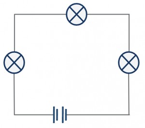 A series circuit illustrating how electricity flows through a single pathway.
Key Characteristics of Series Circuits:
- Current: The same current flows through all components.
- Voltage: Voltage is divided across the components.
- Resistance: The total resistance is the sum of individual resistances.
- Circuit Interruption: If one component fails, the entire circuit breaks, halting current flow.
Parallel Circuits: Multiple Paths for Electricity
Parallel circuits offer multiple pathways for current to flow, with components arranged side by side. Imagine multiple separate water pipes originating from the same source and terminating at the same destination – this represents a parallel circuit.
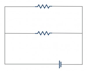 A parallel circuit showing multiple pathways for electrical current.
Key Characteristics of Parallel Circuits:
- Current: Current is divided among the different paths, with the total current equaling the sum of currents through each path.
- Voltage: Voltage is the same across all components.
- Resistance: Total resistance decreases as more paths are added.
- Continuity: If one path is disrupted, current continues to flow through the remaining paths.
Key Differences Between Series and Parallel Circuits
Recognizing the distinctions between series and parallel circuits is vital for understanding their operation.
Current and Voltage: Contrasting Behaviors
In series circuits, the current remains constant throughout, while the voltage is divided among the components. Parallel circuits exhibit the opposite behavior: the voltage is constant across all components, while the current divides based on the number of available paths.
Resistance: How it Changes
Resistance in series circuits accumulates, resulting in a higher total resistance. In parallel circuits, adding more paths reduces the overall resistance, as current has more options for flow.
Reliability: A Critical Factor
Series circuits are vulnerable to failure: if one component fails, the entire circuit ceases to function. Parallel circuits offer greater reliability, as current can still flow through alternative paths even if one path is interrupted.
Practical Applications of Series and Parallel Circuits
The choice between series and parallel circuits depends on the specific application requirements. Series circuits are commonly used when a uniform current is desired. Parallel circuits are favored for their reliability and consistent voltage levels.
Key Vocabulary for Understanding Circuits
Before concluding our exploration of electrical circuits, let’s review some essential vocabulary:
- Voltage (V): The “push” that drives electricity, analogous to water pressure in a pipe. Measured in volts (V).
- Current (I): The flow of electricity, comparable to the amount of water flowing through a pipe. Measured in amperes (amps, A).
- Resistance (R): A property that opposes current flow. Higher resistance results in slower current. Measured in ohms (Ω).
- Circuit: A complete path or loop for electricity to flow.
- Conductor: A material that readily allows electricity to flow, such as most metals.
- Insulator: A material that resists the flow of electricity, such as plastic and rubber.
Conclusion: Powering Our Understanding of Electricity
In summary, we’ve covered the basics of electrical circuits, including how does electricity travel, how to interpret circuit diagrams, and the distinctions between series and parallel circuits. This knowledge extends beyond the classroom, applying to real-world applications in our devices, homes, and cities. You now possess a greater understanding of the electrical forces that shape our world.